MEP and electrical engineers
Communicate system layouts using supported symbols and connections.
Engineering diagramming
Draw engineering diagrams with ready-made symbols. Connect components, edit their properties and export the drawing for your team.
Find your role and the work this tool can help with.
Communicate system layouts using supported symbols and connections.
Prepare process and instrumentation diagrams for technical discussion and review.
Communicate piping, equipment and instrumentation layouts with supported P&ID and MEP symbols. Review connectivity and component information before sharing the diagram.
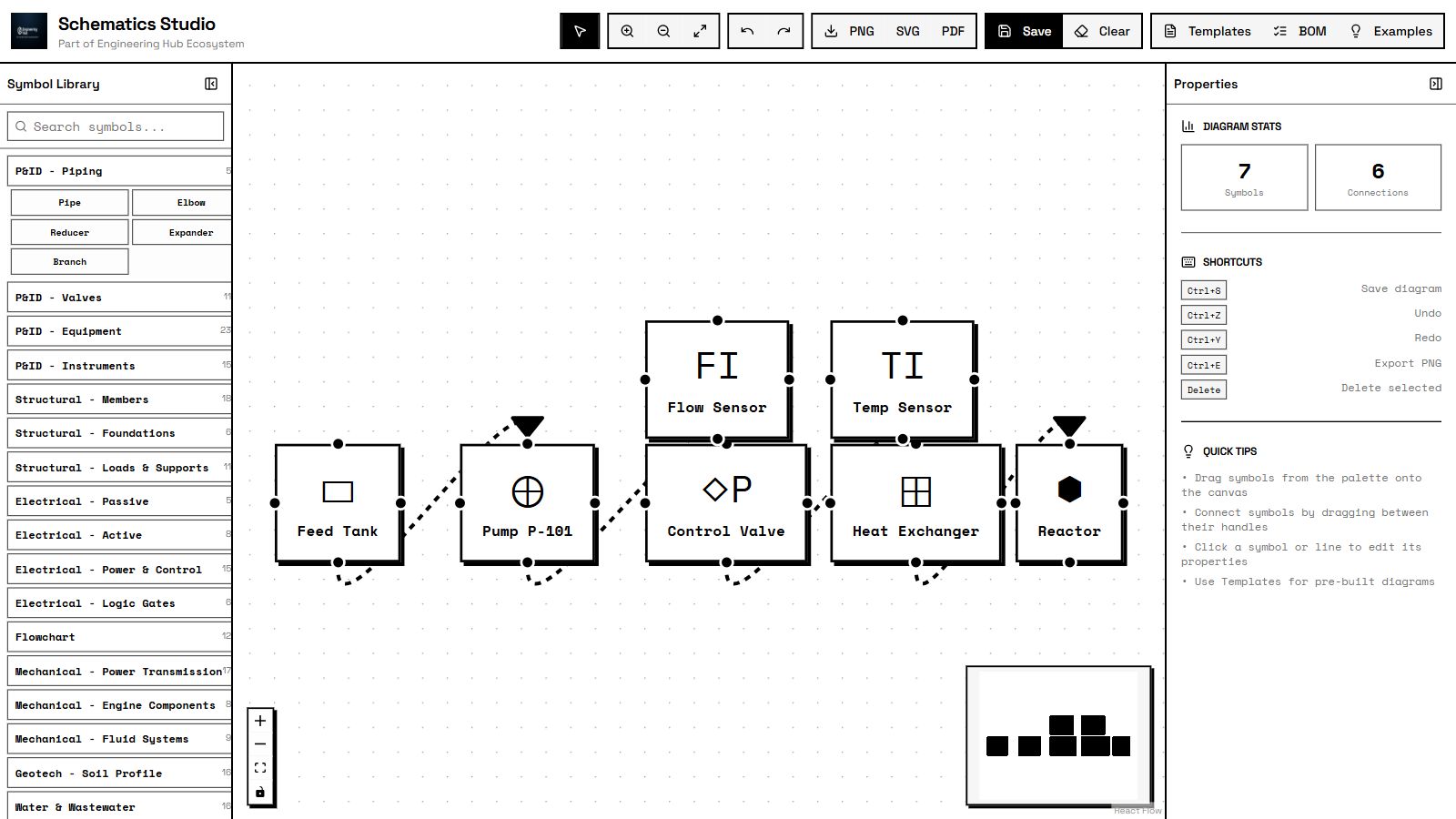
Explain your system with a clear diagram.
Choose symbols or a diagram template.
Connect elements and declare properties.
Review diagram intent and component information.
Export supported formats for technical communication.
Review symbols, connectivity and component specifications. A diagram communicates intent; it does not establish analysis or compliance.
Continue with the related task. Each tool has its own inputs and review requirements.
Check the supported methods and outputs. If you need help deciding, tell us what you’re working on.